Open roasting project (2) [DIY]
And this is the second part of our open coffee roasting project. Let’s not waste any time. Grab a pair of wire cutters and a screwdriver.

Ripping the popper apart
I’m in a mood to ruin a new, perfectly functioning device. How about you?
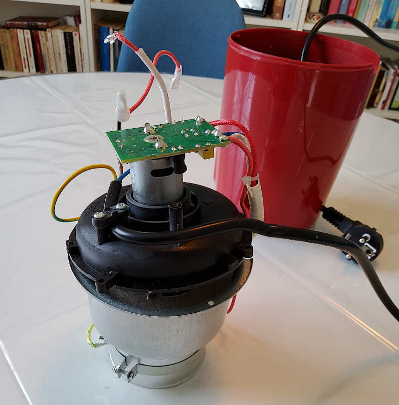
This is the right time to grab your popcorn machine and take it apart. After removing the 2 or 3 screws that close the box, and after cutting the power wires (needless to say, your machine must be unplugged for this operation), you should end up with a little unit looking like this:

You will notice that in the photo I have not yet cut off the power cord. Don’t panic, I’ll do it. And we’ll go even further: with a soldering iron, we’ll remove the printed circuit board at the base of the motor. To do so, we just have to unsolder the two big pins at the centre.
Keeping only what is necessary
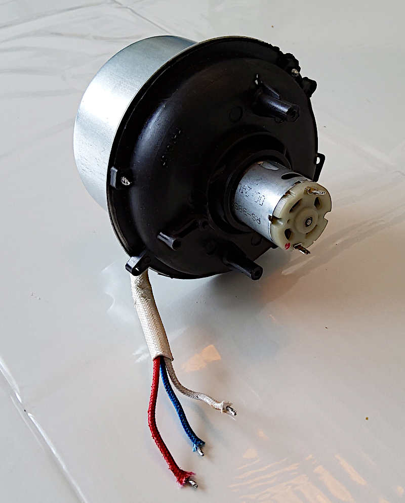
As you can see, all we have left is a motor and a heating element. The latter is composed of two resistors, which explains why we have three wires instead of two (one ground and two hot).

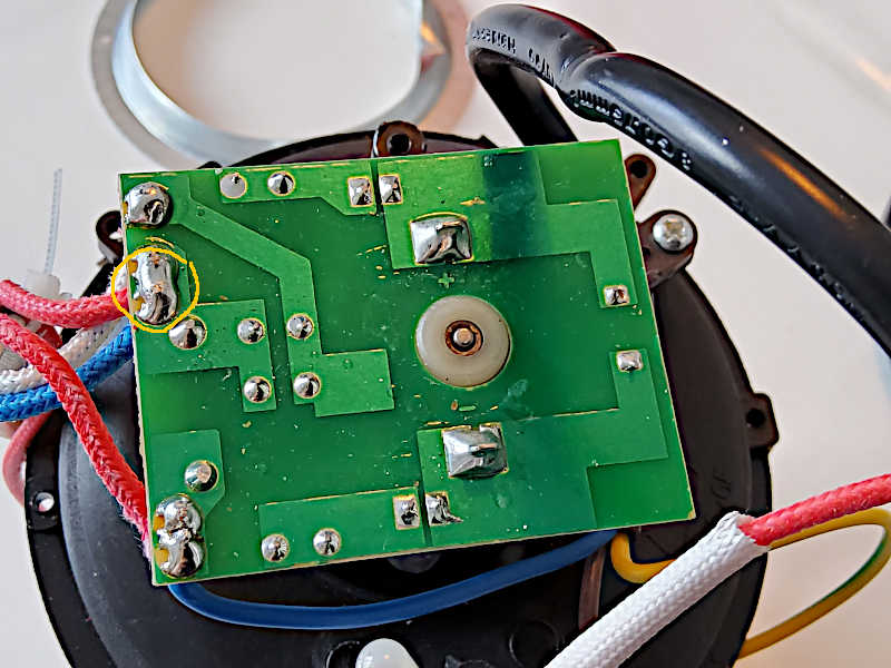
The circuit board reveals that these two elements were originally connected in series. There is only a diode bridge to rectify the current but there is no step-down voltage. In fact, the heater will take the current it needs (probably 200V) and leave the remaining 20V to the motor. But beware, the latter works in DC, so it will have to be powered that way.
On my unit, a red dot marks the + (hot) pole. On the side, it is possible to read the motor reference, which can be useful to refer to the manufacturer’s datasheet.
Linking the two heating resistances together
As mentioned above, the heating element is made of two resistors. If we take a look at the circuit, we can see that two wires (here red and blue) are soldered together.

When we get to the point of powering this element, we will simply reconnect them together, thus, we will end up with a classic two wires element. You know what, let’s do this now.
First mission accomplished
Well, there you go. It wasn’t long. Now all you have to do is solder four long wires (two to the heater and two to the motor) and put the unit back in its box. We will now be able to control these two elements separately.